Sensors consist of two parts: a transmitter and probe.
The two parts are connected by a cable. An icon will be shown on the right of the WARP display panel indicating that the two parts are connected. See image 1.

Room Ambient Temperature & Humidity Sensors and PT1000 Internal Mapping Temperature Sensor do not have an external probe.
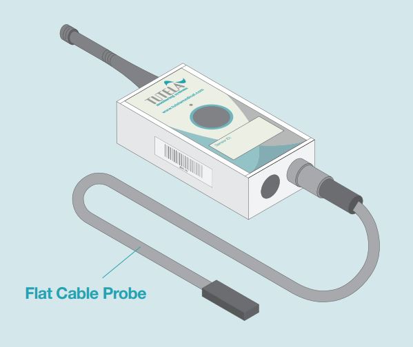
Probes
Probes measure parameters such as temperature, humidity, pressure, CO2, etc. See image 2.
See Types of Sensors for full details.
If a Probe Is Disconnected from Its Transmitter
If a probe is disconnected from its transmitter, for example, if the cable is disconnected or damaged:
-
The sensor will be unable to monitor your equipment
-
Relevant contacts will receive a probe failure alarm (see Probe Troubleshooting for instructions on how to resolve the issue)
-
An open circuit icon will be shown on the right of the WARP display panel (see image 3)
If you receive a probe failure alarm, please respond to the incident as soon as possible to avoid potential data loss.
If a Probe Short Circuits
If a probe short circuits, for example, if it becomes damaged:
-
The sensor will be unable to monitor your equipment
-
Relevant contacts will receive a probe failure alarm (see Probe Troubleshooting for instructions on how to resolve the issue)
-
A short circuit icon will be shown on the right of the WARP display panel. See image 4.
If you receive a probe failure alarm, please respond to the incident as soon as possible to avoid potential data loss.


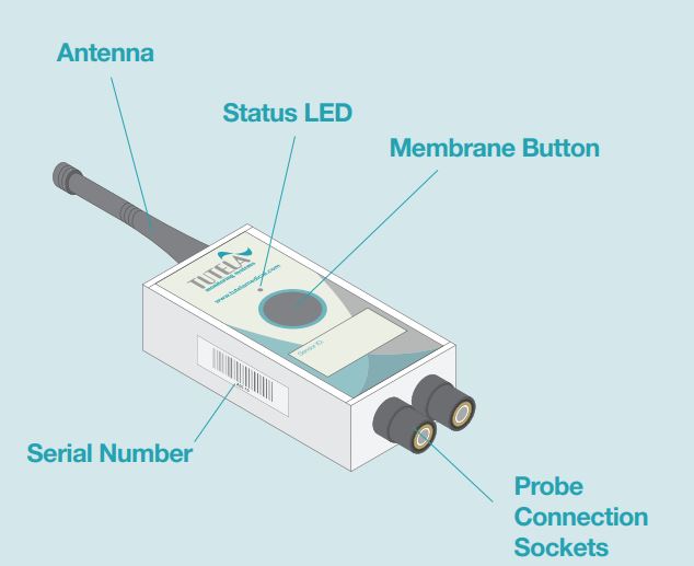
Transmitter
The transmitter powers the probe and sends readings to the WARP. See image 4.
They have the following features:
Membrane Button
The membrane button is located on the front of the device.
If the membrane button is pressed and released, the transmitter will reset/re-establish a connection with either a signal repeater or WARP and immediately send the current probe value to the WARP.
Status LED
The status LED is located above the membrane button.
It does not illuminate unless you press and release the membrane button.
Following release of the membrane button, the LED will flash once:
-
Green - indicating that the transmitter is communicating with the WARP
-
Red - indicating that the transmitter is not communicating with the WARP
Probe Connection Sockets
Probe connection sockets are located on the bottom of the transmitter.
Channel A is located on the left.
Channel B is located on the right.
Some transmitters may have two probes attached.
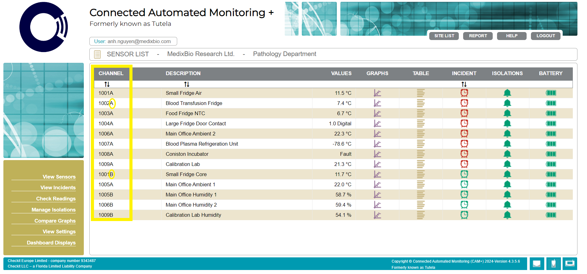
The probe channel is displayed on the sensor list page. See image 5.
Antenna
The antenna transmits data to the WARP.