Follow the steps below to install a Cloud Connector.
Register the Cloud Connector in the Control Centre
You must be an Administrator to register a Cloud Connector in the Control Centre.
The device you use to complete the steps below must have a camera to scan the QR code on the Cloud Connector.
-
Log in to the Control Centre.
-
Go to Devices > Maintenance.
-
Select the location where you want to connect the Cloud Connector, then click Continue.
-
Click Add new device.
-
In the Device Range dropdown, select SenseFlex.
-
In the Sensor Type dropdown menu, select Cloud Connector.
-
Click the right arrow.
-
Scan the QR code on the back of the Cloud Connector. You will see a message confirming that the device has been found.
-
Click the right arrow to continue.
-
(Optional) Add a description, for example, “In main office”
-
Click the right arrow to continue. You will see a message stating that the device has been registered.
-
Click the right arrow to continue. You will see a message stating that the device has been successfully installed.
Mount the Cloud Connector
The Cloud Connector can be mounted to a wall/ceiling or suspended from a drop ceiling. Follow the appropriate instructions below.
Mount to Wall/Ceiling
-
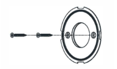
Secure the mounting bracket to the wall/ceiling with screws (see image 2).
If mounted below 2 meters, the adhesive can be used alone.
-
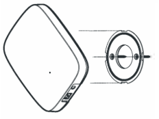
Align the slots and place the Cloud Connector onto the bracket (see image 3).
-
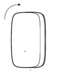
Turn the Cloud Connector 45° to secure it in place (see image 4).
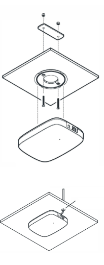
Drop Ceiling Installation
-
Remove the tile from the ceiling.
-
Attach the mounting plate to the tile using two screws and nuts.
-
Align the slots and place the Cloud Connector onto the bracket.
-
Turn the Cloud Connector 45° to secure it in place.
-
Drill a 15 mm cable hole, 6 cm from the edge of the device.
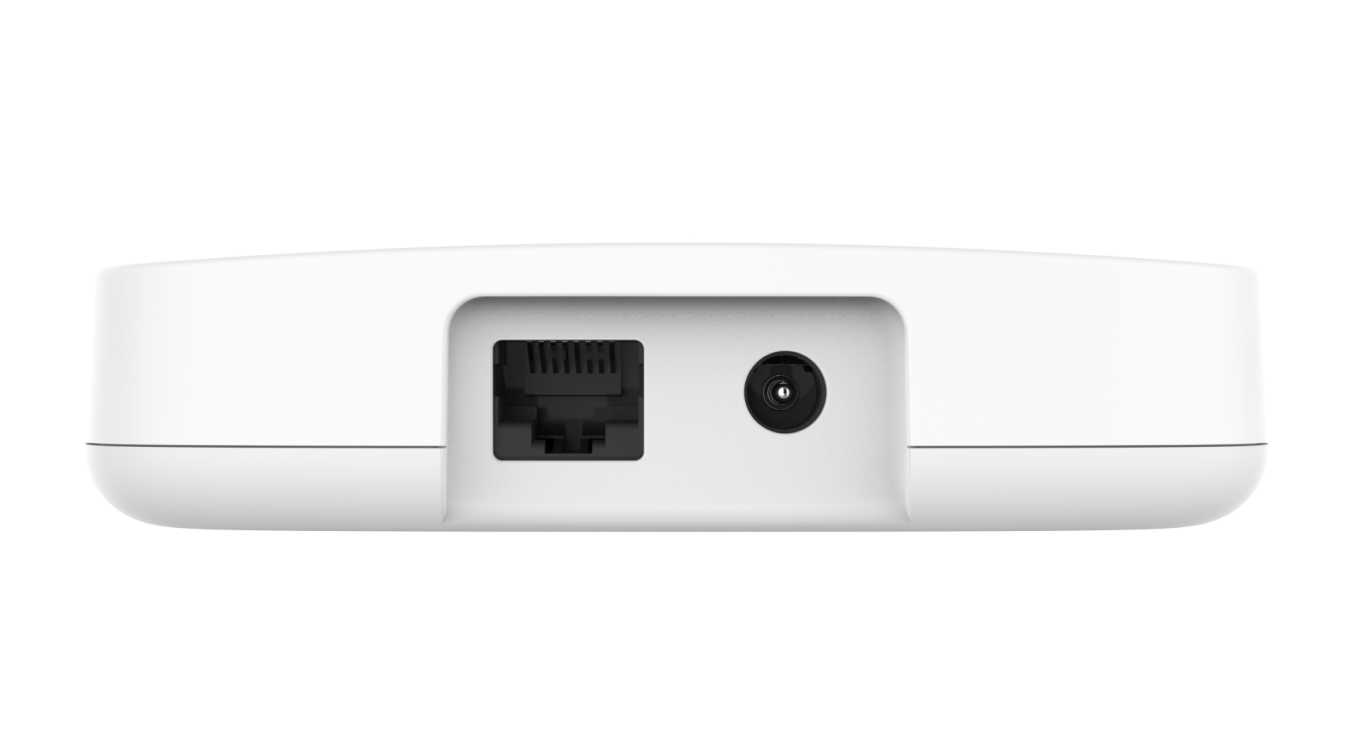
Connect the Cloud Connector to the Power Supply & Internet
-
Connect the power cable to the bottom of the Cloud Connector and the power outlet.
If you intend to power the device using a PoE splitter and do not want an additional power source, skip this step.
-
Connect the Ethernet cable to the bottom of the Cloud Connector and an open Ethernet socket.
If you intend to connect to the internet using only cellular connectivity, skip this step.
-
Wait for 5 minutes.
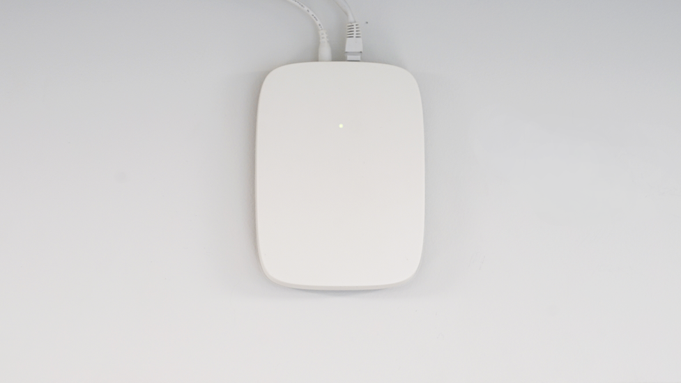
-
Check the LED on the front of the device. If it is:
-
Solid white: The device has been successfully installed. Continue to Step 4: Install Sensors.
-
Flashing white: The device is connecting to the internet/updating. This may take a few minutes.
-
Red: The device is not connected to the internet.
-
Visit the Status Page to determine if there are any service disruptions or planned maintenance.
-
If you connect via Ethernet, ask your IT department to ensure that they have completed Step 1: Prepare the Network.
-
-
Not illuminated: The device is powered off. Ensure that the device is connected to the mains power supply. If the device is still unable to power on, contact us.
-